Overview
ARM stands for Acorn RISC machine, based on the company’s name started ARM designing back in 1983.
ARM Holdings’ primary business is selling IP cores, which licensees use to create micro controllers (MCUs) and CPUs based on those cores
In this article we will be studying ARM7TDMI in detail, as studying all could be little too much. ARM7TDMI is the most successful implementation of ARM with hundreds of millions sold. Most ARM variants are developed on top of this.
I. Features
- RISC (Reduced Instruction set)
- High performance, low power and small size
- load/store architecture
- Pipelining
- Uniform and fixed length instructions
- ALU and Shifter control
- Multiple load/store register instructions
- Coprocessor instruction interface
- THUMB support (16-bit dense compressed instruction set)
- 7 Processor Modes
II. PIPELINING
Usually ARM instructions are executed in 3 stages :
1. Fetch : fetch instruction from memory to pipeline
2. Decode : decode the instruction to ARM
3. Execute : ALU result written to destination registers
with latest processor adding two more stages as
Memory access and write back.
So what is pipelining ?, lets understand
Portion of hardware which does fetching of instruction will be idle while decode and execute phase of instruction, this leaves the room for starting the next instruction’s fetch before first instruction finishes the decode or execute phase.
So in optimized way, when first instruction is getting executed, second instruction can be decoded and a third instruction can be fetched. This is what pipelining is. simple !! :).
Below figure will help you memorizing it.
III. Processor Modes
- USER
- Fast Interrupt FIQ
- Interrupt IRQ
- Supervisor SVC
- Abort ABT
- Undefined UND
- System SYS
Lets have some quick understanding of these modes:
Most application program runs in USER mode. A program in user mode unable to access protected system resource, in order to use them mode need to be changed from USER mode to some other mode by raising an exception.
Modes other the USER are called privileged modes.
Modes other then USER and SYSTEM mode are called exception modes.
Processor enters into Privileged modes under specific exception conditions.
Different modes have few different additional registers, to avoid corrupting USER state registers when exception occurs.
SYSTEM Mode have same number of registers as USER mode.
summary :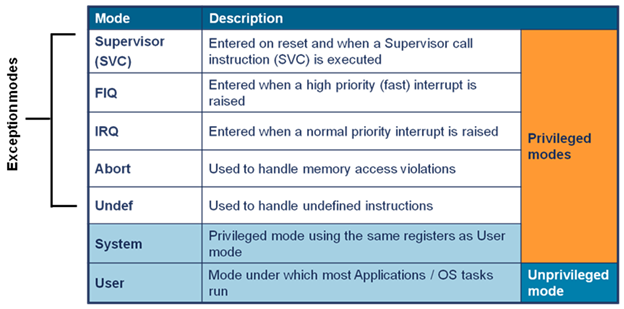
IV. REGISTERS
ARM has 37, 32-bit long registers:
30 – General purpose
5 – SPSR (saved process status register)
1 – CPSR (current process status register)
1 – PC (program counter)
General purpose registers :
15 registers are visible at max in one mode(in USER mode) naming R0 to R14.
R0 to R7 are unbanked registers(ie same physical address across all the modes) R8 to R14 are banked registers(ie separate copy of these registers in different mode if they exist).
Thing to remember is banked register contents are preserved when the mode change and hence no need to save there data.
R13 is used as stack pointer commonly known as SP.
R14 is used as link register to store the return address for exception/sub-routine. If there are multiple nested levels, the previous return address goes to stack, pointed by R13, and the last address is kept in R14.
Program Counter:
R15 is known as PC. PC contains the address of the instruction being executed at the current time.As each instruction gets fetched, the program counter increments by 4 bytes in ARM state and 2 bytes in THUMB state.
Due to pipelining, current executing instruction is typically PC-8 for ARM and PC-4 for thumb.
For ARM state bits 1 & 0 are always 0 or ignored.
For THUMB state bit 0 is always 0 and ignored.
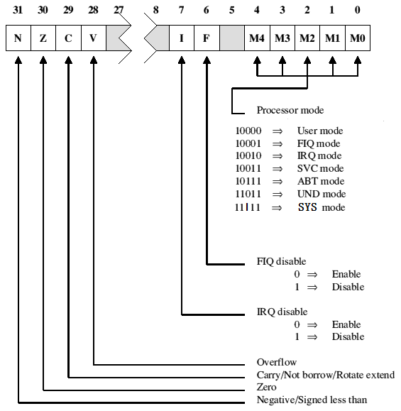
CPSR (Current process status register):
As the name suggest CPSR holds the information of current process.
SPSR(Saved Process status Register):
Used to store CPSR when an exception occurs, each exception mode has its separate SPSR. USER mode and SYSTEM mode doesn’t have SPSR as they need not to execute exception handlers.
Thumb State :
Its a subset of ARM state, In thumb state there is no access to R8 to R12.
Summary:
V. Exceptions
As the processor enters in to an exception mode, some registers are automatically switched depending on the type of mode. This ensure that task state is not corrupted by occurrence of exception.
When an exception occurs ARM completes its current instruction, then :
Step 1 : saves the PC to LR (R14)
Step 2: saves CPSR in new mode’s SPSR
Step 3: changes the mode corresponding to the exception
Step 4: Disable the exceptions of lower priority
Step 5: Load the new mode’s instruction to PC (exception handler or ISR)
A unique address is predefined for each exception handler, address to which processor is forced to branch is called exception/ interrupt vector.
Exception/Interrupt Vector:
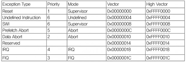
Once the exception is handled by the exception handler, mode is changed back to USER mode and the user task is resumed. Handler program must restore the user state exactly as it was before exception.
Any modified register must be restored from the handler stack.
CPSR must be restored from its SPSR.
PC must be changed back to what it was executing, LR (R14) will help here.
In case multiple exception occurs at same time, depending on there priority they will be serviced.
VI. CORE
Two main blocks Data path and Decoder.
Two read ports to register banks from A-Bus and B-bus and one write port from ALU.
Barrel Shifter : shift/rotate 2nd operand by any number of bits
ALU: Perform airthmatic/logic functions
Address Register and Address incrementer holds either PC address or operand address.
Data register holds read/write data from/to memory
Instruction decoder decodes machine code to control signals
In single cycle, data values are read on bus A & B , and the result from ALU is written to registers.
ARM 7 core has Von Neuman architecture, which means single 32 bit data bus carrying both data and instructions. In latter ARM architectures like ARM9 Harvard architecture is implemented, which means separate buses for data and instructions.
These all were the top view of ARM processor, hope this helps.
Please do let me know your feedback/concern in comment section below.
Saurabh Sengar
mailto: saurabh.truth@gmail.com
* all images used in this blog are from google images search, and I don’t own them
